| Product Overview
KSW-WNS02 Wireless Channel Emulator (also known as 'wireless channel simulator' and 'RF channel emulator') is a kind of simulation equipment used in wireless channel environment, to realize RF channel interconnection and simulation of dynamic wireless channel. According to different testing demands, KSW-WNS02 should have the following functions:
1) Multiple multipoint-to-multipoint RF channel connection;
2) Wireless channel simulation: Simulation of multipath, Doppler frequency shift, fading channel, dynamic delay, interference, signal-to-noise ratio, etc.

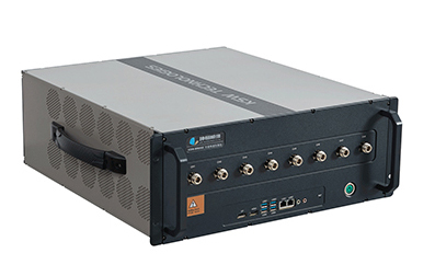
8-CHANNEL WIRELESS CHANNEL EMULATOR

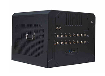
16-CHANNELWIRELESS CHANNEL EMULATOR

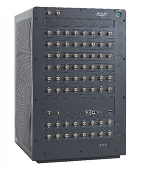
64-CHANNELWIRELESS CHANNELEMULATOR
| Main Features
● Single device supports up to 64 RF duplex channels
● Support maximum 4096 fading channels
● Support up to 500M signal bandwidth
● Support maximum delay of 3s
● Support up to 100dB large scale fading range
● Support short wave, ultrashort wave, and L/S/C/X/Ku/Ka bands
| Applications
● Massive MIMO simulation test
● Phased array antenna test
● Next generation wireless communication channel simulation
● Wireless networking simulation test
● MIMO OTA test
● Satellite, UAV and other semi-physical simulation test
| Main Technical Data
SN | Name | Technical Data |
| 1 | Number of RF channels | 2-64 channels optional, full duplex |
| 2 | Frequency range | 1.5MHz ~ 6GHz or 30MHz ~6GHz |
| 3 | Number of local oscillators | 2 |
| 4 | Channel bandwidth | 2MHz/40MHz /120MHz/500MHz |
| 5 | Number of fading channels | Maximum960 |
| 6 | Maximum number of multipaths for single fading channel | 48 @40MHz/120MHz signal bandwidths
24 @2MHz/500MHz signal bandwidths |
| 7 | Frequency accuracy | 10⁻⁷ |
| 8 | Large scale fading | 100dB |
| 9 | Input signal power range | -40dBm ~ 30dBm |
| 10 | Output signal power range | -120dBm~-10dBm |
| 11 | Output signal power resolution | 0.1dB (output signal power ≥-100dBm) |
| 12 | Output signal power accuracy | ±1dB (output signal power ≥-100dBm) |
| 13 | Delay range | 4us~3s |
| 14 | Delay simulation resolution | 0.1ns |
| 15 | Maximum Doppler frequency shift | ±6MHz |
| 16 | Doppler frequency shift precision | ±0.1Hz |
| 17 | Coded Doppler (optional) | Support maximum bandwidth of 500MHz, maximum speed of 30Mach, and precision of 1Hz |
| 18 | Output signal non-harmonic spurious distortion | ≤-45dBc |
| 19 | EVM | ≤1%@256QAM,100MHz modulation signal, 2GHz frequency point |
| 20 | Background noise | Not higher than -162dBm/Hz@ (Typical) |
| 21 | Channel isolation | 135dB@2GHz (Typical) |
| 22 | RF interface type | N(F) or SMA |
| 23 | I/O port standing-wave ratio | ≤1.6 |
| 24 | Fading channel model | Constant, Rayleigh, Rice, Nakagami, flat, domed, Gaussian, double Gaussian, LOGNORMAL, Suzuki, pure Doppler, Butterworth, custom mode, etc. |
| 25 | Standard channel model | COST207, GSM/EDGE, ITU_R 3G, JTC, HIPERLAN/2, 3GPP LTE, etc. |
| 26 | AWGN/CW interference source simulation | Supported |
| 27 | Continuous phase change | Supported |
| 28 | Automatic calibration function | Supported |
| 29 | Custom dynamic simulation | Supported, with maximum update frequency >1KHz |
| 30 | Dynamic delay update rate | Maximum 2us/ms, with corresponding speed of 600km/s |
| 31 | External reference input interface | 10MHz~100MHz |
| 32 | Internal reference output interface | 100MHz |
| 33 | Dimension (W x H x D) (mm) | 8 channels: 445×177×500 (rack-mounted) 16 channels: 585×463×583 64 channels: 585×853×583
|